An all pass filter is a frequency filter that passes all frequencies and preserves the gain of the signal at every frequency.
As discussed below, although all pass filters have an uninteresting magnitude response (they are not interesting in the way they affect the magnitudes of frequencies in the signal), they may have other useful characteristics.
The simplest all pass filter
A typical finite impulse response filter a(n) of length N, which takes an input signal x(k), produces an output signal y(k) with the formula
$$y(k) = \sum_{n=0}^{N-1} a(n) x(k-n)$$
That is, the output y(k) at sample k is equal to the weighted sum of the current and the N – 1 previous samples of the input x(k), where the N weights are the filter a(n), n = 0, 1, …, N – 1.
The simplest all pass filter then is the filter of length N = 1 given by
$$a(0)=1$$
This filter produces simply
$$y(k)=x(k)$$
and makes no change to the input signal. It is clear that this filter is an all pass filter as any frequency contained in x(k) would remain with unchanged magnitude in y(k). Of course, this filter does not have many practical applications.
Finite impulse response all pass filter
A useful finite impulse response (FIR) all pass filter of some odd length N is
$$a(n)=\begin{cases} 1, & n=\frac{N-1}{2} \\ 0, & n \ne\frac{N-1}{2}\end{cases}$$
Using the weighted sum above with this all pass filter results in the computation
$$y(k)=x(k-\frac{N-1}{2})$$
where y(k) is the output signal at sample k, x(k) is the input signal at sample k, and N is the length of the filter.
The transfer function of this filter, using the Z transform, is
$$H(z)=z^{-\frac{N-1}{2}}$$
It should be clear that this is an all pass filter as any frequency that is contained in the input x(k) will remain in the filter output y(k) with unchanged amplitude. In other words, the magnitude response of this filter, evaluated on the unit circle with z=ej ω, will be
$$|H(e^{j \omega})|=|e^{-j \omega \frac{N-1}{2}}|=1$$
The magnitude response is equal to 1 for all frequencies. This is indeed an all pass filter.
Using finite impulse response all pass filters
Although the all pass filter above produces no change to the magnitude of frequencies, it introduces a delay in each frequency in the input signal x(k) of (N – 1) / 2 samples. We can say that this filter has a delay in phase equal to (N – 1) / 2 samples at every frequency, or (N – 1) / (2 fs) seconds, if the sampling frequency is fs samples per second.
Take a finite impulse response low pass filter of the same length N. It can be shown that, if this filter has coefficients that are symmetric around the middle (N – 1) / 2, it will introduce the same delay in phase of (N – 1) / 2 samples for all frequencies (see phase response). This means that the output of the low pass filter and the all pass filter above can safely be combined. The output of the low pass filter can be subtracted from the output of the all pass filter to produce a high pass filter. The all pass filter passes all frequencies, the low pass filters passes only low frequencies, and the difference between the output signals of the two filters will contain only high frequencies.
Moreover, if aL (n) is the low pass filter and aA (n) is the all pass filter, then the output signal is
$$y(k)=\sum_{n=0}^{N-1}a_A(n)x(k-n)-\sum_{n=0}^{N-1}a_L(n)x(k-n)=\sum_{n=0}^{N-1}(a_A(n)-a_L(n))x(k-n)$$
This means that, rather than first producing the outputs of both filters and subtracting those outputs, we can simply design a high pass filter with coefficients aA (n) - aL (n). For example, given the standard low pass filter
$$a_L(n)=\begin{cases} \frac {\sin(\frac{2\pi f_c(n-\frac{N-1}{2})}{f_s})}{\pi (n-\frac{N-1}{2})}, & n\ne\frac{N-1}{2} \\ 2\frac{f_c}{f_s}, & n=\frac{N-1}{2}\end{cases}$$
we can take the all pass filter above and produce the high pass filter
$$a_H(n)=\begin{cases} \frac {\sin(\frac{2\pi f_c(n-\frac{N-1}{2})}{f_s})}{\pi (n-\frac{N-1}{2})}, & n\ne\frac{N-1}{2} \\ 1-2\frac{f_c}{f_s}, & n=\frac{N-1}{2}\end{cases}$$
Finite impulse response all pass filters then are used for filter transformations – to transform a FIR low pass filter into a FIR high pass filter. This filter transformation is called "inverting the filter" or "spectral inversion of the filter".
Infinite impulse response all pass filter
All infinite impulse response all pass filters with real valued coefficients have the following transfer function.
$$H(z)=z^{-M} \frac{a_N+a_{N-1}z^{-1}+a_{N-2}z^{-2}+...+z^{-N}}{1+a_1z^{-1}+a_2z^{-2}+...+a_Nz^{-N}}$$
where M and N are some nonnegative integers. The magnitude response of this filter, evaluated on the unit circle with z = ej ω, is as follows.
$$|H(e^{j \omega})|=|z^{-M} \frac{a_N+a_{N-1}z^{-1}+a_{N-2}z^{-2}+...+z^{-N}}{1+a_1z^{-1}+a_2z^{-2}+...+a_Nz^{-N}}|$$ $$=|\frac{z^{-M}}{z^{-N}} \frac{a_Nz^{-N}+a_{N-1}z^{-(N-1)}+a_{N-2}z^{-(N-2)}+...+1}{1+a_1z^{-1}+a_2z^{-2}+...+a_Nz^{-N}}|=|e^{j\omega(N-M)}|=1$$
Thus, this is an all pass filter.
Using infinite impulse response all pass filters and the Shroeder all pass filter
We could attempt the filter transformation that we used above to derive the FIR high pass filter also when designing IIR filters. We would have to choose an easy an appropriate all pass filter and that could be difficult, considering that IIR filters do not behave as nicely in the stop band as do FIR filters. The magnitude response of the resulting high pass filter, however, will not be as well behaved. There are better ways to create IIR high pass filters.
A more useful example of an infinite impulse response (IIR) all pass filter is the Shroeder all pass filter. The Shroeder all pass filter has the transfer function
$$H(z)=\frac{g+z^{-N}}{1+gz^{-N}}$$
and computes the output y(k) from the input x(k) with the equation
$$y(k)=g \, x(k)+x(k-N)-g\,y(k-N)$$
where g is some gain and N is some delay in number of samples. The magnitude response of this all pass filter is flat, as before. Its impulse response, however, is much more interesting. The following graph shows the impulse response of the Shroeder all pass filter with g = 0.7 and N = 20 samples, given the sampling frequency 2000 Hz (20 samples at 2000 Hz is equivalent to 10 milliseconds).
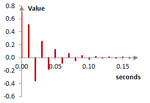
The Shroeder all pass filter creates multiple repetitions of the signal with ever decreasing amplitude. This all pass filter is then used to simulate the multiple repetitions that exist in natural late reverb (see Reverb). Typically, several consecutive Shroeder all pass filters are followed by several parallel feedforward comb filters to produce the Shoreder late reverb. Alternatively, several parallel Shroeder-Moorer low pass feedback comb filters are followed by several consecutive Shroeder all pass filters. The repetitions of the Shroeder all pass filters are very close together and in great multitude, which helps to simulate the diffusion of late natural reverb. In this case, g is typically set around 0.7 and N set to introduce delay of 100 / 3k milliseconds, k = 1, 2, …. That is, N introduces a delay of approximately 33 ms, 11 ms, 3 ms, and so on. Care is taken to select N that are mutually prime in the several all pass filters so that the all pass filter repetitions do not coincide often.
A special case of the Shroeder all pass filter, with N = 1, can be used in phasers.
General formulations of all pass filters
In the general complex number case, finite impulse response all pass filters have the transfer function
$$H(z)=e^{j\phi}z^{-M}$$
and infinite impulse response all pass filters have the transfer function
$$H(z)=e^{j\phi}z^{-M}\frac{b_N+b_{N-1}z^{-1}+b_{N-2}z^{-2}+...+z^{-N}}{1+a_1z^{-1}+a_2z^{-2}+...+a_Nz^{-N}}$$
where ϕ is a constant phase, M and N are nonnegative integers, b1 is the complex conjugate of a1, b2 is the complex conjugate of a2, and so on. In the real number case ϕ = 0 or ϕ = π.
Comments
Older comments
admin: First posted on 2011 09 19
Eric Overton, 2019 09 19: Good piece. All-pass networks get some coverage in most analog electronics courses where they're addressed as op-amp implementations and analyzed in the "s" domain. You don't see them tackled that often in discrete time or a domain other than anything Laplacian.
Add new comment